In rail-related applications, electrical testing is not only essential to prove the safety and reliability of new and modified electrical systems, it can also be a valuable tool for the prediction and prevention of costly failures. Let's explore some of the test equipment most applicable to the rail sector.
Electrical test equipment which is of particular value in railway applications include insulation testers, battery testers, low resistance ohmmeters and time-domain reflectometers (TDRs). Such instruments are widely available and most organisations involved in railway projects are likely to have access already to some, if not all of them. However, it is worth noting that older instruments in particular may not offer the full benefits that are provided by the latest products:
Rail Test Equipment
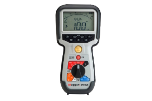
Insulation Testers
 |
 |
| MIT430/2 Insulation Tester |
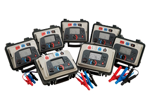
MIT515, MIT525, MIT1025 Insulation Testers |
| CAT IV for electrical and industrial maintenance engineers |
5 kV, 10 kV, 15 kV DC insulation resistance testing |
| Features |
Features |
- Insulation testing up to 1000 V and 200 GΩ range
- Stabilised insulation test voltage (New)
- Single range, faster continuity testing from 0.01 Ω to 1 MΩ (New)
- 600 V TRMs AC and DC voltage measurement
- Live circuit detection and protection, and more...
|
- Measures up to 30 TΩ
- Safety rated up to CAT IV 1000 V to 3000 m
- Unique dual-case design - additional user protection
- Operates from battery or AC mains supply
- Rapid charge Li-ion battery
- Advanced memory with time / date stamp, and more...
MIT515, MIT525, MIT1025 Insulation Testers
|
Battery Testers
 |
 |
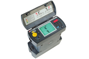
| BITE2 Battery Impedance Tester |
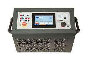
TORKEL Battery Load Testers |
| Determines lead-acid battery cell health up to 2000 Ah |
Battery Discharge Test Systems |
| Features |
Features |
- On-line testing with Pass/Warning/Fail calculations
- Measures impedance, interconnection resistance and cell voltage
- Windows CE operating system with 32 MB of memory
- Measures float and ripple currents
- Includes PowerDB LITE Management Software, and more...
|
- Discharge testing for full insight into battery capacity
- Enhanced safety features including spark free connection and emergency safety fuse
- Ability to test the battery without disconnecting it from the system
- Operates from battery or AC mains supply
- High discharge capacity shortens the test time
- A complete stand-alone discharge test system, and more...
910, 930, 950 TORKEL Battery Load Testers
|
Low Resistance Ohmmeters
Time-Domain Reflectometers (TDRs)
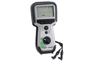 |
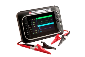 |
| TDR1000/3 Time-Domain Reflector |
TDR2000/3 and TDR2010 |
| Advanced handheld single channel TDR |
Advanced dual channel TDR |
| Features |
Features |
- Designed for use on all metallic cable pairs
- Simple operation
- AUTO set up for instant use
- Ultra fast pulse for near end fault identification
- Trace HOLD feature to allow comparison between cables
- IP54 rating offers real life working
- and more...
|
- Locate faults on paired metallic cables
- AUTO set up mode for instant, easy use
- AutoFind and FindEnd functions helps find the fault fast
- Trace tagging facility that allows a name to be saved with the trace
- Distance dependent gain to counteract signal attenuation
- IP54 rating offers real life working
- and more...
TDR2000/3, TDR2010
|
Other Rolling Stock Test Equipment
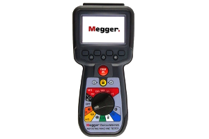 |
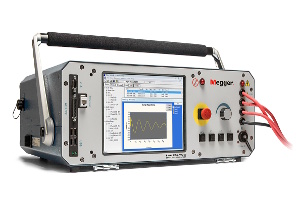 |
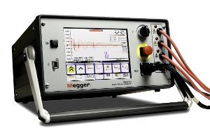 |
| MTR105 Rotating Machine Tester |
Baker AWA-IV Static Motor Analyser |
Baker DX Static Motor Analyser |
| Multiple capabilities in one hand-held device |
Perfect for surge, winding resistance, Megohm, PI, DA, continuous ramp DC step-voltage, and DC hipot tests |
Tests the electrical condition of motors and coils |
| Features |
Features |
Features |
- Insulation resistance / low resistance / motor rotation tester and LCR meter
- Full colour graphic display
- 3 Phase insulation resistance
- Temperature correction for insulation resistance
- Guard terminal
- DLRO four wire Kelvin
- Continuity and diode test
- Capacitance and inductance, and more...
|
- Range includes 2 kV, 4 kV, 6 kV and 12 kV models
- 12 kV HO (high-output) version for performing surge tests on large motors and generators
- IEEE- and IEC-compliant surge test
- Surge waveform comparison
- Inter-turn assessment capabilities and more...
|
- Comprehensive range of tests in one instrument
- Configurable to meet needs and price point
- 4 kV to 12 kV for wide spectrum of motors and coils
- Compatible with the Baker PPX Power Packs for testing up to 40 kV
- High and low voltage tests to characterize circuits and insulation, and more...
|
 |
 |
 |
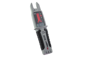
| MET1000 Electrical Tester |
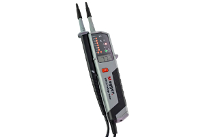
TPT420 Voltage Tester |
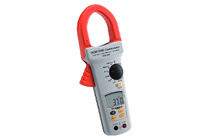
DCM1500 TRMS Clamp Multimeter |
| All-in-one TRMs electrical tester |
Easy-to-use voltage indicating instrument |
DC and AC current measurement up to 1500 A |
| Features |
Features |
Features |
- LED and LCD display with self-test
- Detachable Test Probes
- AC/DC Voltage to 1000V
- 200A AC measurement
- True RMS on ACV/ACA
- Inrush Current
- Phase Rotation, and more...
|
- CAT IV/1000 V
- 12 - 1000 V AC
- 12 - 1500 V DC
- IP64 Rated
- Continuity test function with visual and acoustic indication
- Voltage indication with no batteries, and more...
|
- True RMS measurement for greater accuracy
- Large jaw size improves safety when working with uninsulated conductors
- 750 V AC and 1000 V DC
- Resistance, continuity and frequency measurement, and more...
|
Network Rail have approx. 18,000 lineside buildings which are critical to the continued operation of the network; some housing Switchgear and HV Equipment.
Substation Testing (Rail)
Cable Testing & Diagnostics (Rail)
Taken from a Megger Application Note: Railway Electrical Systems
RAIL BONDING APPLICATION
Railway Electrical Systems
In the UK, we have two common power systems supplying locomotives. A 25 kV overhead line system and a 750 V third rail system. Both systems use the track as a return path for current flow (see Fig 1 and 2).

Fig 1: Overhead line power supply to a train

Fig 2: Third rail supply to trains (broken at crossing point to prevent electrocution)
The traction return can be implemented in multiple ways. However, it is worth noting that you can expect at least one rail to act as a return path (see Fig 3). This will be earthed to prevent the rail voltage rising to a dangerous level (see Fig 4). Sometimes the second rail will act as a parallel return path. In other areas, it will not form part of the power system at all. Instead being used as a signalling conductor.
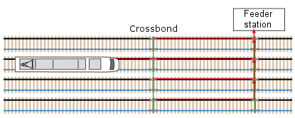
Fig 3: Crossbonded traction return rails

Fig 4: Deliberate connection from rail to earth. Without it, the voltage between the rails and earth would rise to significant potentials.
When more than one rail is used as a return path for current flow, the rails are crossbonded at regular intervals in order to prevent rises in ground potential (see Fig 3).
Crossbonds distribute the return current over the tracks, reducing the return impedance, and lowering rail voltage. They also reduce the impact of a missing bond or break in the traction rail. The rail voltage can also be reduced by adding more parallel conductors (such as an Aerial Earth Wire (AEW)).
Earthing and Bonding
These are the reasons that adequate earthing and bonding is required:
- Human protection
- Functional
- Lightning Protection
- EMC
The risks associated with poor earthing and bonding systems are as follows:
- Safety of the general public
- Employee H&S
- Employee engagement
- Customer experience
- Financial
- Environmental
- Reputation
The UK’s Electricity at Work Regulations specify the following ABSOLUTE (meaning must be done) requirements with regard to earthing and bonding of an electrical system.
Integrity of referenced conductors:
“If a circuit conductor is connected to earth or to any other reference point, nothing which might reasonably be expected to give rise to danger by breaking the electrical continuity or introducing high impedance shall be placed in that conductor unless suitable precautions are taken to prevent that danger.”
The suitable precautions mentioned in this absolute requirement may be met by undertaking a programme or regular testing.
Connections:
“Where necessary to prevent danger, every joint and connection in a system shall be mechanically and electrically suitable for use.”
Testing the resistance of joints and connections in a system upon installation would help to prove compliance with the above requirement.
The railway electrical systems are a small proportion of the cost compared to a railway’s civil infrastructure. Therefore, it will not significantly affect a project's budget by allowing the funding for testing. But, it will help to ensure compliance with the Electricity at Work Regulations and subsequently make sure that railway staff and the public are safeguarded against electric shock.
Railway Bonding - Why test?
Commuters expect a reliable service. As a result, there is constant pressure to reduce delays and cancellations. This is understandable, when considering that research found UK train delays to cost passengers 3.6 million hours in 2016 (Lancefield, 2017).
This has a significant impact on rail industry revenue. Rail line disruption can cost as much as £3 million per day, in some locations (BBC News, 2018).
Routine testing can reduce the risk of unexpected failures, and the high costs associated with them. As can thorough testing during installation.
For further reading on the following topics from the Megger Application Note - Click Here.
- Key concerns:
- Lightening strikes
- Ground Potential Rises (GPR)
- Reducing the rail voltage at the crossbond itself
- List of potential causes of bond resistance increases
- In-service failure of bonds
- Earth mat bonds
- Bonds in high risk areas
- Live conductor joints
Railway Bonding - Testing must take place overnight
A final key concern for railway earthing and bonding is that, where possible, all maintenance is performed overnight. Always on site, it will be outdoors and could occur during poor weather conditions. This is vital to minimise disruption to commuters. However, it puts maintenance staff on a strict schedule. Any work they do must be made good for trains to run the following morning. As such, any test equipment must be quick and simple to use, even in poor lighting/weather.
Railway Bonding - What needs testing?
Ideally, all bonds should be tested periodically to predict failures before they occur. In practise this is a large undertaking. So there should be an emphasis on thorough testing of bonds upon commissioning. Recording results for future comparison. During service, areas of high risk should be considered as candidates for periodic testing. This will allow for monitoring the trend in resistance measurements. As a result, future failures can be identified and repaired before they pose a danger or disruption.
These are some of the particular areas that periodic testing should focus on:
- Resistance of cross bonds
- Resistance of bridge bonds
- Resistance of live conductor joints
- Resistance of earth mat bonds
Fig 15 shows some of the failures that can be avoided by routine testing.
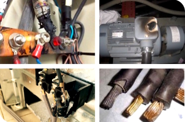
Fig 15: Overheated connections due to high resistance.
Cross bonds are often inspected visually and unfortunately testing is often neglected. Visual inspection is important but it will typically only identify faults that are already quite severe. A quick resistance measurement can indicate an increasing resistance before it becomes noticeable to the eye. Enabling a minor repair to be carried out at the maintenance team’s convenience. Rather than rectifying a major failure at short notice.
There is often a focus on the losing of a bond. Rather than being concerned about an increase in resistance across the bond. The former may be more noticeable and appear a more immediate concern. But the latter can be equally dangerous as it poses a fire risk. In the event of a fault causing current to flow through the bond to earth. The amount of current will be limited by the resistance of the bond. If high resistance, a situation could occur in which the fault current is not high enough to instantaneously activate a circuit breaker. However, the current could still be significantly higher than the rating of the earth path. Enough to cause a fire. Therefore, it is important that the effect of increasing resistance in a bond be considered. Not just the concern of losing the bond completely.
Here are some typical tests to be performed on railway earthing and bonding systems:
- Soil/electrode resistance
- Step and touch potential
- Earth fault loop impedance (EFLI) or prospective fault current (PFC) at feeder stations
- Bond resistance
Rail Application - Selecting an Instrument
Care should be taken when selecting a test instrument to ensure the measurements will be adequate for the application.
Possible sources of error include:
- Lead resistance
- Contact resistance
- External influences, such as:
- Temperature
- Noise ratio and induced currents
- Thermal EMF / Seebeck voltage
- Surface leakage due to contamination
- Hotspot effects
True low resistance testers will overcome lead and contact resistance with a four terminal measurement. Most of the external influences can be overcome by selecting an instrument with a higher test current (as high as is practical for the situation) and a bidirectional test mode. The test current used should not exceed the rated current of the equipment under test. Up to this point, higher test currents give better possibilities to obtain reliable test results.
In addition, the instrument should be suitable for use in the environments it will be used in. Such as, having a sufficient Ingress Protection (IP) rating and being sufficiently rugged for use on site.
So in summary...
Failed bonds can have a significant impact on rail industry revenue. Rail line disruption can be very costly. Both financially and to the service provider's reputation with commuters. Not to mention the safety concerns associated with bond failures. Testing during commissioning and routine testing can reduce the risk of unexpected failures and detect missing or high resistance bonds.
Megger offer a range of low resistance ohmmeters to measure bond resistance to a high degree of accuracy in harsh environment (such as the DLRO10HD in Fig 15). In addition, Megger manufacture a wide range of earth resistivity and Earth Fault Loop Impedance (EFLI) test equipment.
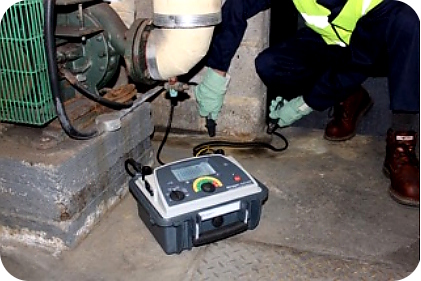
Fig 16: The heavy duty DLRO10HD taking a measurement
Remember that the railway electrical systems are a small proportion of the cost compared to a railway’s civil infrastructure. Why take risks when the cost of testing will add little to a project’s cost?
For the full list of referenced material and to read the full RAILWAY ELECTRICAL SYSTEMS - RAIL BONDING APPLICATION NOTE Click Here.
Photo by Jonas Tebbe on Unsplash